
-Diagnostic Codes can be monitored using Caterpillar ET Software, but typically may also be viewed using the Display/ Monitor, eg. CAT Messenger, Murphy Power View, Advisor/ Vision, etc.
-MID is what control is activating code.
-CID points to the circuit that is malfunctioning.
-FMI describes the fault.
Sensor Diagnostics
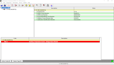
Understanding the diagnostic code is key in determining the fault. Access active diagnostic codes using ET or the monitor (if available). The ECU designation displays the ECU with which ET is communicating. You may also see the ECU designation as part of a three segment code. For example, the “1836-3” above may be displayed as “36-1836-3”. In this case, “36” would be the Module Identifier (MID), and would represent the “Engine Control #1”.
The Component Identifier (CID) identifies the electronic circuit at fault. In this example, “1836” represents the Auxiliary Temperature Sensor.
The Failure Mode Identifier (FMI) identifies the type of fault that is present. In this example, “3” represents a “Voltage Above Normal”.
There are many FMIs available for diagnostic codes, common FMI codes include:
* FMI 03 – Voltage Above Normal
* FMI 04 – Voltage Below Normal
* FMI 05 – Current Below Normal
* FMI 06 – Current Above Normal
* FMI 08 – Abnormal Frequency, Pulse Width Or Period
It is important to note that FMIs do not indicate the root cause; rather, FMIs indicate the condition that exists. For example, an FMI 03 “Voltage High”, or “Voltage Above Normal”, does not indicate that the ECU has detected an open (root cause), though an open may cause this fault. The ECU has only detected that the voltage on the signal wire is higher than the normal. There are causes to consider when troubleshooting this FMI, such as a short to battery power or other power supply
(sensor power supply).
For sensor diagnostics, there are only three possible components that can be the root cause: the sensor, wiring/connectors, or ECU. Of all electronic related failures, the most common root cause failed components are harnesses/connectors, followed by sensors and ECUs.
It is important to follow good troubleshooting procedures to ensure that good sensors and ECUs are not mistakenly replaced. Following good troubleshooting procedures leads to identification of the root cause of a problem. Finding and repairing the root cause eliminates the unnecessary replacement of good parts, reduces warranty costs, and ensures that the problem has been fixed, rather than masked.
When using ET, monitor active diagnostic codes and determine what condition is present. Always start at the suspect sensor. If the code indicates “Voltage High” or “Voltage Above Normal”, check the supply voltage, then short the signal circuit to ground (B to C). If the code indicates a “Voltage Low” or “Voltage Below Normal”, check supply voltage, then open the signal circuit (B and/or C). Always try to get the ECU to activate the opposite code than the one that is present. Remember, when a code is active, there can only be three faults: sensor, wiring, or ECU.
Diagnosing a “Voltage Low” or Short Condition (FMI 04)
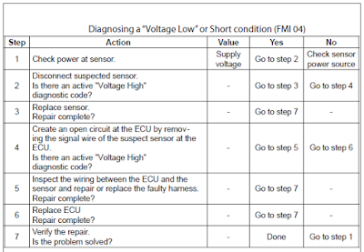
When diagnosing a “Voltage Low”, first check for power (Step 1). If power is present, then disconnect the suspected sensor (Step 2). Check for an active “Voltage High” diagnostic code. Allow approximately 15 seconds for any codes to activate.
If the code changes from a “Voltage Low” code to a “Voltage High” code, then the harness and the ECU are functioning properly and the sensor is faulty (Step 3).
Temporarily connect a new sensor then check for active diagnostic codes. If the new sensor fixes the problem, reconnect the suspect sensor. If the problem returns, permanently install the new sensor. Verify that the repair eliminates the problem (Step 7).
With the suspect sensor disconnected, if the code does not change from a “Voltage Low” code to a “Voltage High” code, then there is a short between the sensor and the ECU or the ECU is faulty (Step 4). With the suspect sensor disconnected, create an open circuit at the ECU by removing the signal wire of the suspect sensor from the ECU. Check for active diagnostic codes. If a “Voltage High” code becomes active after disconnecting the signal wire, there is a short in the wiring between the ECU and the sensor.
Inspect the wiring between the ECU and the sensor and repair or replace the faulty harness (Step 5). Verify that the repair eliminates the problem (Step 7).
If there is still a “Voltage Low” code (short) after disconnecting the signal wire, connect a new ECU.
If the new ECU fixes the problem, reconnect the suspect ECU. If the problem returns, permanently install the new ECU (Step 6). Verify that the repair eliminates the problem (Step 7).
Diagnosing a “Voltage High” Condition (FMI 03)
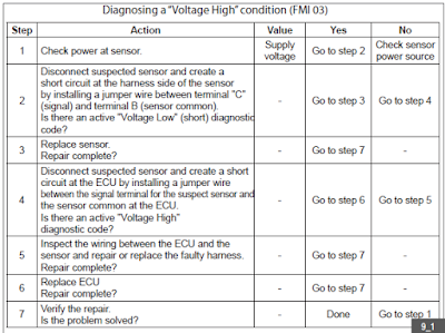
When diagnosing a “Voltage High”, check for power (Step 1). If power is present, disconnect the suspect sensor and create a short circuit at the harness side of the sensor (Step 2). Install a jumper wire between terminal “C” (signal) and terminal “B” (sensor common) on the harness side of the sensor connector. Wait approximately 15 seconds for activation of a code.
If a “Voltage Low” diagnostic code (short) is active when the jumper is installed, the engine harness and the ECU are functioning properly (Step 3). Temporarily connect a new sensor. If the new sensor fixes the problem, reconnect the suspect sensor. If the problem returns, permanently install the new sensor. Verify that the repair eliminates the problem (Step 7).
If the “Voltage High” diagnostic code remains active when the jumper wire is installed, remove the jumper wire and create a short at the ECU by installing a jumper wire between the terminal for the signal of the suspect sensor and the sensor common connection at the ECU (Step 4). Wait approximately 15 seconds for activation of any code.
If the “Voltage High” diagnostic code is not present, the ECU is operating properly and there is an open in the wiring between the ECU and the sensor. Inspect the wiring and connectors between the ECU and the sensor and repair or replace the faulty harness components (Step 5). Verify that the repair eliminates the problem (Step 7).
If the “Voltage High” code is still active when the jumper wire is installed, temporarily connect a test ECU (Step 6). If the test ECU fixes the problem, reconnect the suspect ECU. If the problem returns, permanently install the new ECU. Verify that the repair eliminates the problem (Step 7).
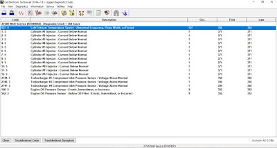
Diagnosing an “Abnormal Frequency, Pulse Width, Or Period” (FMI 08) code.
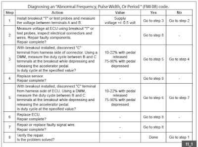
Abnormal signal codes do not indicate an voltage high or voltage low state. To diagnose abnormal signal codes, install a breakout “T” or test probes (spoons) and measure the voltage between terminals “A” and “B” (Step 1). If the measured voltage is not supply voltage, the sensor is not receiving the correct voltage. Measure the voltage at the ECU using the breakout “T” or spoons. Inspect the electrical connectors and wires and repair or replace the faulty components (Step 2). Verify that the repair eliminates the problem (Step 8). If the measured voltage is supply voltage (± 0.5 volt), measure the signal at the harness side of the connector (Step 3).
With the breakout installed, disconnect the “C” terminal from the harness side of the connector. Using a DMM, measure the duty cycle between “B” and “C” at the breakout while depressing and releasing the accelerator pedal. If the duty cycle is not present or out of range, temporarily install a new sensor (Step 4). If the new sensor eliminates the problem, reconnect the suspect sensor. If the problem returns, permanently install the new sensor. Verify that the repair eliminates the problem (Step 8).
If the duty cycle is between 10% and 22% while the pedal is fully released, and between 75% and 90% while the pedal is fully depressed, reconnect the “C” wire and measure the signal at the ECU (Step 5).
Using the appropriate ECU breakout or terminal probes (spoons) at the ECU connector, remove the signal wire from the ECU on the harness side. Measure the duty cycle between the signal and sensor return pin (sensor return pin must be connected to the ECU during this test) with a DMM while depressing and releasing the pedal. If the duty cycle is between 10% and 22% while the pedal is fully released, and between 75% and 90% while the pedal is fully depressed, temporarily connect a test ECU. If the problem is resolved with the test ECU, reconnect the suspect ECU. If the problem returns, permanently install the new ECU (Step 6). Verify that the repair eliminates the problem (Step 8).
If the duty cycle is not present or out of range, there is a problem with the pedal position sensor signal wire (Step 7). Repair or replace the faulty wiring. Verify that the repair eliminates the problem (Step 8).
NOTE: ECUs are rarely faulty. Before replacing an ECU, make sure to visually inspect P1 and P2 for any sockets that may not be fully seated. Unseated sockets will prevent an accurate reading when using test probes; therefore, it is critical to perform the 10 pound pull test.
Event Codes
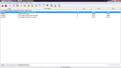
Event codes differ from diagnostic codes. Event codes are used to indicate that some operational problem has been detected by the ECU. Usually, this does not indicate an electronic malfunction. Examples of event codes would be “Low Engine Oil Pressure” or “High Coolant Temperature”, as opposed to a diagnostic code, which could be “Engine Oil Pressure Sensor Shorted” or “Coolant Temperature Sensor Open Circuit”.
You do not troubleshoot an event code in the same way you do a diagnostic code. Refer to the applicable Troubleshooting Guide for specific information on event code causes and repair steps.