Important: SPS programming of vehicle controllers is not supported in GDS2. For SPS Pass Through programming with the J2534 interface tool, use the TIS2Web SPS application.
GDS2:
GDS2 is designed for use by trained service personnel to diagnose and repair automotive electronic systems. Every attempt has been made to provide complete and accurate technical information based on factory service information available at the time of publication. However, the right is reserved to make changes at any time without notice. To familiarize yourself with GDS2 and its capability, and how to use it, please read through the User’s Guide before putting the GDS2 to work.
GDS2 provides the following capabilities in multiple languages:
* Read codes, code status, Freeze Frame data and Clear Codes.
* Read VIN, ECU part numbers and software numbers.
* Record, store and replay Stored data.
* Control and monitor Output Control functions.
* Configure and Reset functions.
* Record or display history of the previous vehicle diagnostic sessions.
Tis2web:
TIS has six major applications:
* Software Download (SWDL)
* Service Programming System (SPS)
* Calibration Information (SPS Info)
* Security Access (Security)
* Snapshot (Snap)
* Global Diagnostic System (GDS)
Depending on what access user profile you have and what region you are from, additional icons may appear.
Service Programming System (SPS)
The Service Programming System (SPS) updates the flash calibration files that are stored in a vehicle onboard controller (e.g. PCM, ABS, VTD). The calibration file custom-tailors a module to a certain vehicle. The calibration file contains data such as spark curves and fuel control. When troubleshooting a drivability condition, diagnosis may call for reprogramming the controller with newer calibration information to correct a customer concern.
The Service Programming System (SPS) updates the flash calibration files that are stored in a vehicle onboard controller (e.g. PCM, ABS, VTD). The calibration file custom-tailors a module to a certain vehicle. The calibration file contains data such as spark curves and fuel control. When troubleshooting a drivability condition, diagnosis may call for reprogramming the controller with newer calibration information to correct a customer concern.
Programming Tool Interface
The SPS application is part of the TIS2Web system. To program an ECU, the SPS application must communicate with the vehicle control modules using the proper J2534 programming interface tool. A Programming Interface tool is your connection between your computer and the vehicle’s J1962 DLC connector for pass-thru programming of the vehicle’s ECUs.
The following are the supported interface tools:
* Tech 2 Scan Tool
* MDI interface
* J2534 Programming Interface Tool
The following are four generally used types of serial communications used with an ECM/PCM controller:
* UART (Universal Asynchronous Receive and Transmit)
* Class 2
* Keyword
* GM LAN
Note: If your J2534 device has wireless capability, it is recommended to use the hardwired interface of the programming tool while programming an ECU.
Selecting the Correct Calibration
When reprogramming a vehicle, selecting the correct calibration is critical. You will only see calibrations that are valid for the VIN entered. Be sure to check the history of each calibration. The history lists an explanation of the calibration file, telling what the calibration is for and whether it supersedes any other calibrations. It is helpful to read the latest bulletins to stay up to date on why certain calibrations have been released. Related bulletin numbers are sometimes listed along with the calibration files.
Based on the calibration history and bulletins, select the appropriate calibration file. For many vehicles, you will also need to complete the multiple tab selections. Each tab is for a distinct calibration file. An unchecked box on a system tab indicates that a necessary selection has not been made.
If you need a VCI number, contact your Customer Support Center. Once you have the VCI number, it must be entered in the entry screen when requested by the SPS.
The general three-part process for SPS programming is as follows, regardless of the vehicle involved:
* Check the vehicle’s control module to determine which, if any, calibration file is currently stored.
* Determine if an update is required.
* Transfer the selected data to the vehicle’s control module.
Caution: Prior to performing SPS, it is important to heed the following precautions:
* Using an outdated version could damage vehicle modules. The J2534 interface tool and the terminal must have the latest software.
* Make sure the vehicle battery is fully charged. Battery voltage for SPS should be between 12 and 14 volts. Due to the time requirements of programming a controller, connect a fully charged 12V jumper or booster pack disconnected from the AC voltage supply. DO NOT connect a regular battery charger.
* Stable battery voltage is critical during programming. Any fluctuation, spiking, over voltage or loss of voltage will interrupt programming.
* Make sure the cable connections are secure. A disconnected cable MAY cause controller failure.
* In using a laptop computer/other display device (PDA etc.) for pass-thru programming, ensure that the power supply is properly connected. If powered by AC and the power cord becomes disconnected, it could interrupt programming and cause damage to the control module. If the laptop is operating from its internal power source (batteries), then make sure it is adequately charged to complete the SPS process.
Note: ECU to be programmed must be installed in the vehicle before beginning this process.
Performing Pass-Thru Programming
Pass-thru programming requires that the Scan Tool remain connected to the terminal and to the vehicle throughout the programming process. The vehicle must be in close proximity to the terminal while using pass-thru programming.
Note: TIS2Web only supports Pass-Thru Programming with the J2534 interface tool / Tech2.
Pass-Thru Programming Procedure
* Connect a fully charged 12V jumper or booster pack disconnected from the AC voltage supply. DO NOT connect a regular battery charger.
* Launch TIS2Web.
* From the TIS2Web main screen, select the Service Programming System icon.
* Power ON the scan tool.
* Key on, battery fully charged.
* Select “Start SPS”.
* If hardware screen does not appear, check Tech2 hardware connections. This process could take some time depending upon your internet connection. You will be requested to perform an SPS software update, if one is required.
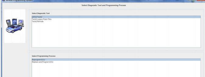
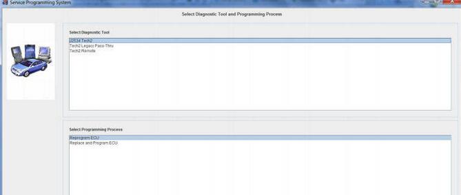
* Select Diagnostic Tool
* Select Programming Process
* Select Next
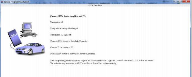
* Connect the Scan Tool to the vehicle and computer. Select Next.
Note: You may receive a message that states: “Please restart your programming interface and press OK to retry: Press cancel to abort!” It is important to close all programs including TIS2Web when performing SPS to allow programming to continue.
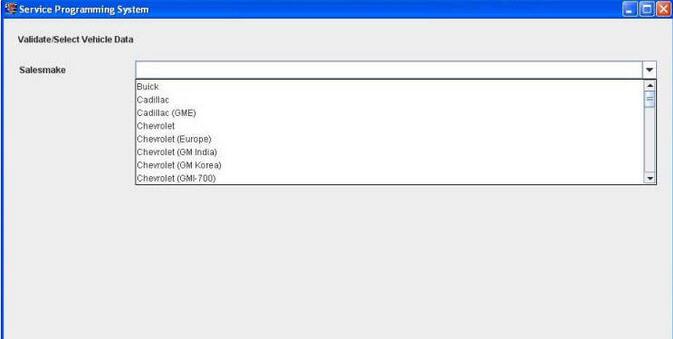
* Select the Sales Make of the vehicle. Select Next.
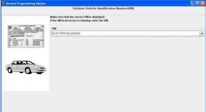
* You may or may not receive a pop-up screen. Ensure correct VIN is displayed. If VIN is incorrect or missing enter the correct. Select Next.
Note: In order to reduce the potential for signal loss, the J2534 interface tool should be configured for the most stable communication option at your location.
Note: The J2534 interface tool may have wireless capability, however it is recommended when using a programming interface tool to program an ECU that it is hardwired to the programming tool which contains the SPS application.
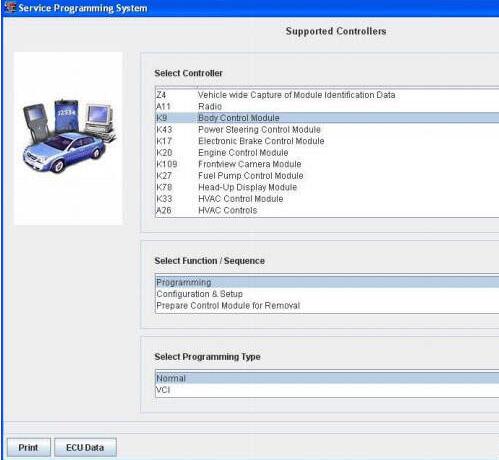
* At the Supported Controllers screen:
* Select the appropriate control module under “Select Controller”, e.g. PCM / VCM Control Module etc.
* Select the appropriate programming type (Normal, VCI).
* Select “Next” Note: For VCI programming you will need to contact the ACDelco Aftermarket Support Center.
* During communication a “validate /select vehicle data” screen will appear. You may or may not get a pop-up screen.
* At the Calibration Selection screen: Select the appropriate calibration(s).
* Make sure all folder tabs have a green check mark.
* Select “Next”.
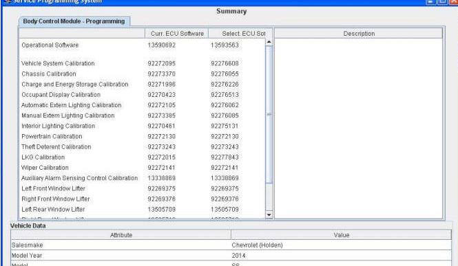
* At the Summary screen: Verify current calibration(s) with selected calibration(s).
The current calibration is displayed along with the new calibrations available for the selected vehicle.
Note: If you are attempting to reprogram a vehicle with the same calibration, a pop up window will appear. In most cases reprogramming will not be required. Select Cancel to stop if reprogramming is not required, otherwise continue on with the procedure. General Motors does not recommend reprogramming with the same calibration.
Select “Next”.
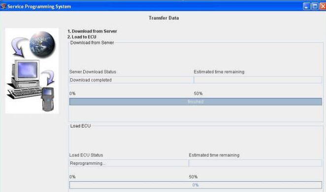
Caution: To help avoid damage to the vehicle controllers, DO NOT turn the ignition off during a reprogramming event unless instructed to.
The Transfer Data screen appears as reprogramming begins, finishing when the percentage bar reaches 100?percent. Time may vary depending upon calibration. Estimated remaining programming time will appear on the screen.
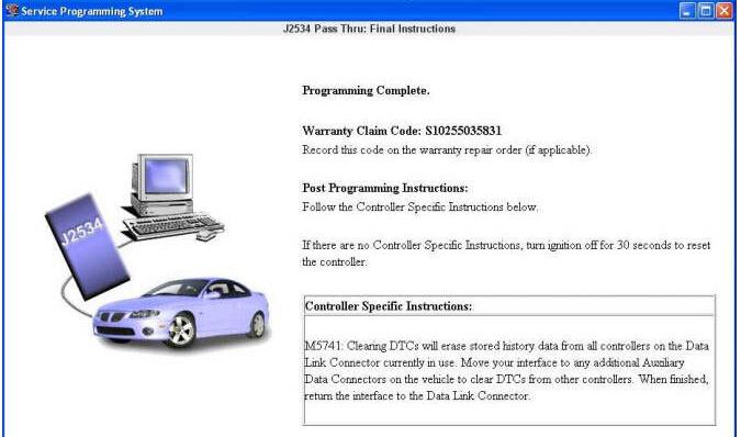
* The Program Controller “Programming Complete” screen appears.
A Warranty Claim code will appear if applicable.
A Warranty Claim Code is a 5 digit code which is unique for each programming event and is required to be documented on a submitted warranty claim.
* Select “Clear DTCs” to erase history data. The program will return to the TIS2Web main screen. Be sure to verify successful reprogramming.
Note: DTCs may set during programming. Clear DTCs after programming is complete.
* Turn off the Scan Tool. Select “Cancel”.
Note: Some vehicles will require that Idle Learn, TP Learn, Theft Deterrent Relearn, or Camshaft Variation Learn procedures be performed after programming. Consult the appropriate service information for these procedures.
* Disconnect the GM Scan Tool from the vehicle.